
Recommend
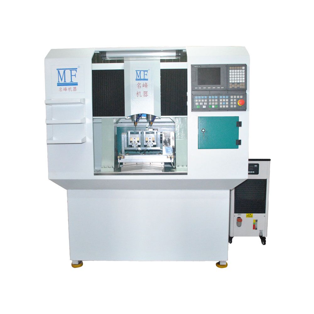
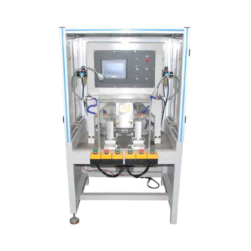
Five-axis double-head multi-function CNC...
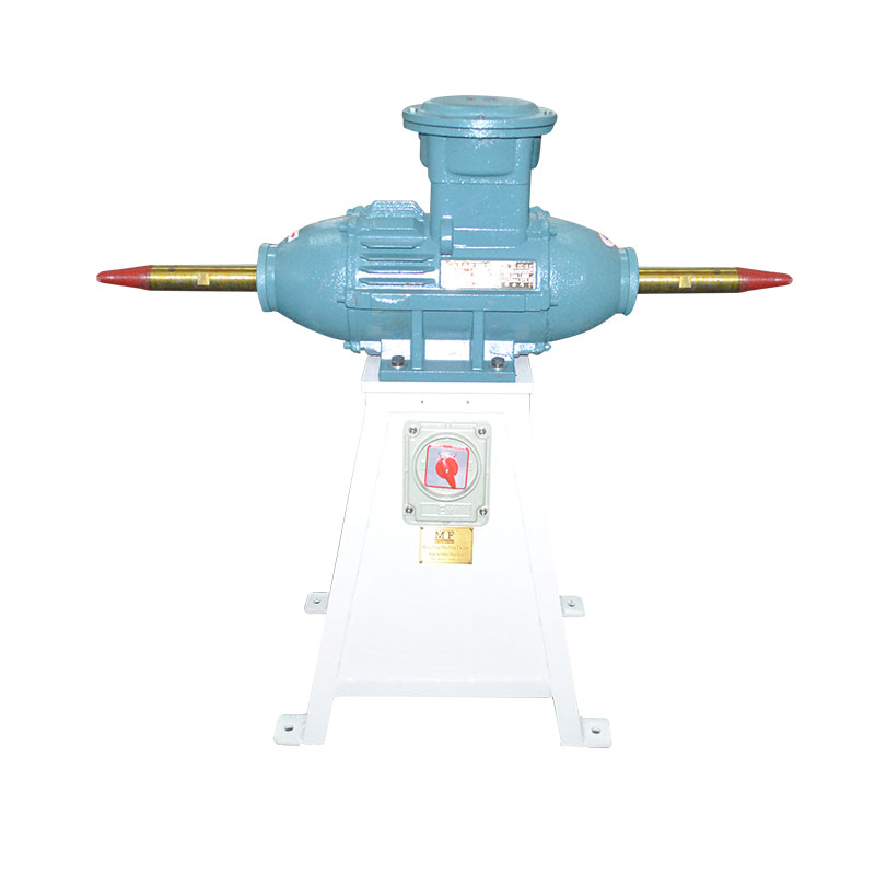
Gold frame explosion-proof polishing...
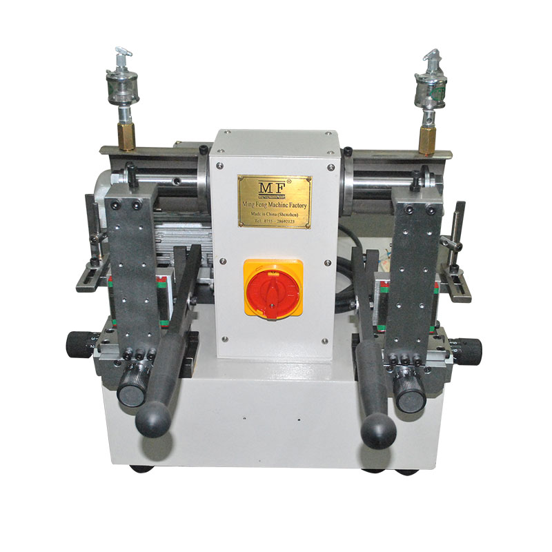
New dual axis copper core machine
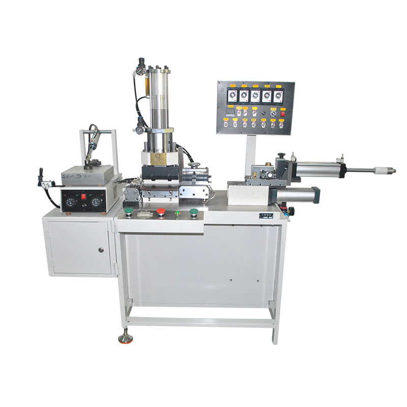
Manual Pile Cutting Machine II
Explosion-proof polishing machine for...
Environment-friendly double-head cutting...
Environment-friendly high-speed gong...
High-speed gong machine
Single axis copper core machine
New dual axis copper core machine
Nail glue machine
Planer
Hydraulic punching machine
Wind oil pressure planer
The new automatic three-sided planing...
Common problem HOME >> News >> Common problem
The utility model relates to the field of spectacle frame processing equipment, in particular to a high-efficiency fully automatic numerical control spectacle frame processing equipment.
Background technique:
Glass frame processing is generally divided into two processes, the inner frame of the frame (the installation position of the lens) is the first process, and the outer frame of the frame (the outline of the frame) is the second process.
Existing eyeglass frame processing machines first perform the first processing procedure and then the second processing procedure. The two procedures cannot be performed at the same time, and the working efficiency is low.
In view of the above situation, the applicant applied for a utility model patent named "A Full-automatic CNC Spectacle Frame Processing Machine" with the application number 201620617181.7 in June 2016, which provides a two-step process that can be carried out simultaneously. The fully automatic CNC glasses frame processing machine to improve the work efficiency of the equipment.
However, the applicant found that the processing speed of the inner frame of the frame will be faster than the processing speed of the outer frame of the glasses. Often the inner frame of the glasses is processed and the outer frame of the glasses is still being processed, which will affect the processing efficiency of the frame.
Technical realization elements:
In view of the above-mentioned shortcomings, the purpose of the present invention is to provide a fully automatic numerical control glasses frame processing equipment with high processing efficiency.
In order to achieve the above purpose, the technical solution adopted by the utility model is:
A high-efficiency fully automatic numerical control spectacle frame processing equipment, including a frame, characterized in that: a first longitudinal rail is provided on the frame, and a second longitudinal direction parallel to the first longitudinal rail is provided on the left side of the first longitudinal rail A guide rail, a first horizontal guide rail perpendicular thereto is provided on the right side of the first longitudinal guide rail;
The first longitudinal rail is provided with a sliding eyeglass frame fixing fixture and the first spectacle outer contour processing fixing fixture; the second longitudinal rail is provided with a sliding eyeglass outer contour machining fixation fixture;
The first horizontal rail is provided with an eyeglass inner frame processing knife set device slidingly matched with the eyeglass inner frame processing knife set device, which is used for processing the eyeglass inner frame processing material to be processed on the eyeglass inner frame processing fixing jig;
A second transverse guide rail is also provided above the first longitudinal guide rail and the second longitudinal guide rail, and the second transverse guide rail is provided with a first glasses outer contour machining knife set device and a second glasses outer contour machining Knife set device, the first spectacle outer contour machining knife set device is used to process the spectacle outer contour of the material to be processed on the first spectacle outer contour processing fixing jig, and the second spectacle outer contour processing knife set device is used for the second spectacles External contour processing The material to be processed on the fixed jig performs the external contour processing of the glasses.
The present invention is further provided that the spectacle inner frame processing knife set device includes a seat body slidingly engaged with the first lateral guide rail, and the seat body is provided with a cutting knife movable in the vertical direction.
The utility model is further provided that the glasses inner frame processing knife set device is also provided with a first manipulator. The first manipulator is used to grab the material to be processed and put it into the glasses inner frame processing fixing jig for fixing.
The utility model is further provided that the first spectacle outer contour processing knife set device and the second spectacle outer contour processing knife set device both include a seat body 2, the seat body 2 and the second horizontal guide rail are slidingly matched, and the seat body 2 is upper There is a cutting knife 2 which can move in the vertical direction.
The utility model is further configured such that a second manipulator is provided on both the first spectacle outer contour processing knife set device and the second spectacle outer contour processing knife set device, and the second manipulator is used to fix the spectacle inner frame processing fixture The to-be-processed material is moved to the first eyeglass outer contour processing fixing jig and the second eyeglass outer contour processing fixing jig to be fixed.
The present invention is further provided that the second lateral guide rail is a rotatable screw.
The beneficial effects of the utility model:
The high-efficiency fully automatic numerical control spectacle frame processing equipment provided by the utility model has two sets of spectacle outer contour processing devices corresponding to one set of spectacle inner frame processing devices, which solves the problem that the spectacle inner frame is processed slowly due to the slow processing The problem that the processing device needs to wait, by using the above technical solution, improves the working efficiency of the eyeglass frame processing equipment.
Description of drawings
Figure 1 is a schematic diagram of the structure of the utility model;
Figure 2 is a schematic structural view of the utility model eyeglass inner frame processing knife set device;
FIG. 3 is a schematic diagram of the structure of the first spectacle outer contour machining knife set device and the second spectacle outer contour machining knife set device of the present invention.
detailed description
The following describes the specific implementation of the present invention in further detail with reference to the accompanying drawings and embodiments. The following embodiments are used to illustrate the present invention, but are not used to limit the scope of the present invention.
The utility model will be described below with reference to FIGS. 1 to 3.
A high-efficiency fully automatic numerical control spectacle frame processing equipment, including a frame 1, a first longitudinal rail 2 is provided on the frame, and a second longitudinal rail parallel to the first longitudinal rail 2 is provided on the left side of the first longitudinal rail 2 3. The right side of the first longitudinal rail 2 is provided with a first transverse rail 4 perpendicular thereto; the first longitudinal rail 2 is provided with a fixing fixture 5 for processing the inner frame of the eyeglass and the outer contour of the first eyeglass Processing fixing jig 6; the second longitudinal rail 3 is provided with a second eyeglass outer contour processing fixing jig 7 slidingly matched with it (the specific structure of the eyeglass inner frame processing fixing jig and the eyeglass outer contour processing fixing jig is specified in the application number 201620617181.7 Has been disclosed in the utility model patent); the first horizontal rail 4 is provided with an eyeglass inner frame processing knife set device 8 slidingly matched with the eyeglass inner frame processing knife set device 8 for processing the eyeglass inner frame processing fixing fixture 5 The material to be processed is processed on the inner frame of the glasses; above the first longitudinal rail 2 and the second longitudinal rail 3, a second horizontal rail 9 is also provided. The second horizontal rail 9 is provided with a sliding fit The first spectacle outer contour machining knife set device 10 and the second spectacle outer contour machining knife set device 11, the first spectacle outer contour machining knife set device 10 is used to process the material to be processed on the first spectacle outer contour processing fixing jig 6 For the outer contour processing of glasses, the second outer contour processing cutter set device 11 is used to process the outer contour of the glasses on the material to be processed on the fixing jig 7 for the second outer contour processing of the second glasses.
The glasses inner frame processing fixing jig 5, the first glasses outer contour processing fixing jig 6, the second glasses outer contour processing fixing jig 7, the glasses inner frame processing cutter set device 8, the first glasses outer contour processing knife set device 10, the first The movements of the second glasses outer contour processing knife set device 11 are controlled and driven by a numerical control system to realize XYZ axis processing.
The eyeglass inner frame processing knife set device 8 includes a seat body 81 slidingly engaged with the first lateral guide rail, and the seat body 81 is provided with a cutting blade 82 movable in the vertical direction. A first manipulator 83 is also provided on the eyeglass inner frame processing knife set device 8, and the first manipulator 83 is used to grab the material to be processed and put it into the eyeglass inner frame processing fixing jig 5 for fixing.
The first spectacle outer contour machining knife set device 10 and the second spectacle outer contour machining knife set device 11 each include a seat body 101, and the seat body 101 and the second lateral guide rail 9 are slidingly fitted. A cutting blade two 102 moving in the vertical direction, the first spectacle outer contour machining knife set device 10 and the second spectacle outer contour machining knife set device 11 are each provided with a second manipulator 103, and the second manipulator 103 is used to put glasses The materials to be processed in the inner frame processing fixing jig 5 are moved to the first eyeglass outer contour processing fixing jig 10 and the second eyeglass outer contour processing fixing jig 11 for fixing, and the second lateral guide rail 9 is a rotatable screw rod.
The above is only the preferred embodiment of the utility model. It should be pointed out that for those of ordinary skill in the art, without departing from the technical principles of the utility model, several improvements and modifications can be made. The above assumption These improvements and modifications should also be regarded as the scope of protection of the present invention.
Previous:Making method of glasses nail ...
Next page:Maintenance method of glasses ...
What is the manufacturing method of the automatic glasses foot bending machine?
2020-05-21
The formation of the eyewear industry
2020-05-21
The origin and development of glasses
2020-05-21
Making method of glasses nail hinge machine
2020-05-21
Manufacturing method of high-efficiency automatic numerical control glasses frame...
2020-05-21
Contact: Miss Shen
Mobile: +86-13509635423
TEL: +86-0755-28692123
FAX:+86-0755-28692277
E-mail:chinamf@mf789.com
Address: No. 35, Dayuan Street, Silian Community, Henggang Street, Longgang District, Shenzhen

WeChat scan code
SHenZHen Mingfeng Machinery Equipment Co. ,Ltd. Shenzhen Mingfeng machine equipment Co. Ltd.Copyright 2016-
Mingfeng Machine © Copyright
Technical Support:XINQI
 English
 简体中文
简体中文 HOT searches: