
Recommend
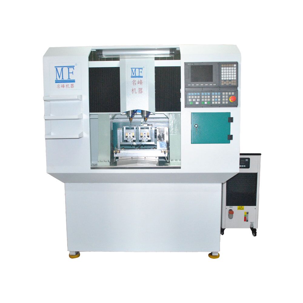
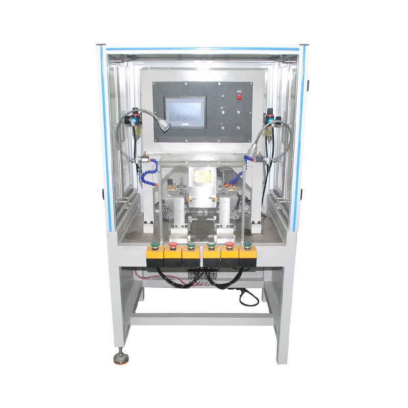
Five-axis double-head multi-function CNC...
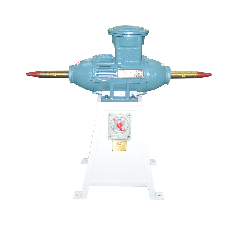
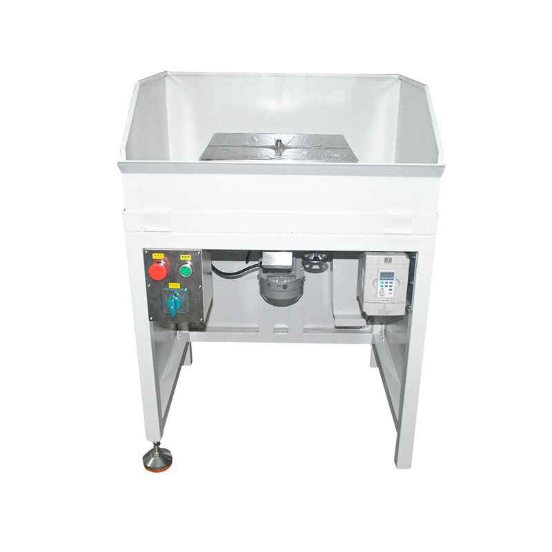
Gold frame explosion-proof polishing...
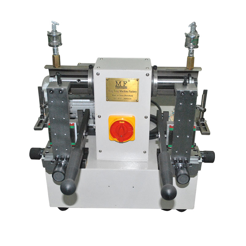
New dual axis copper core machine
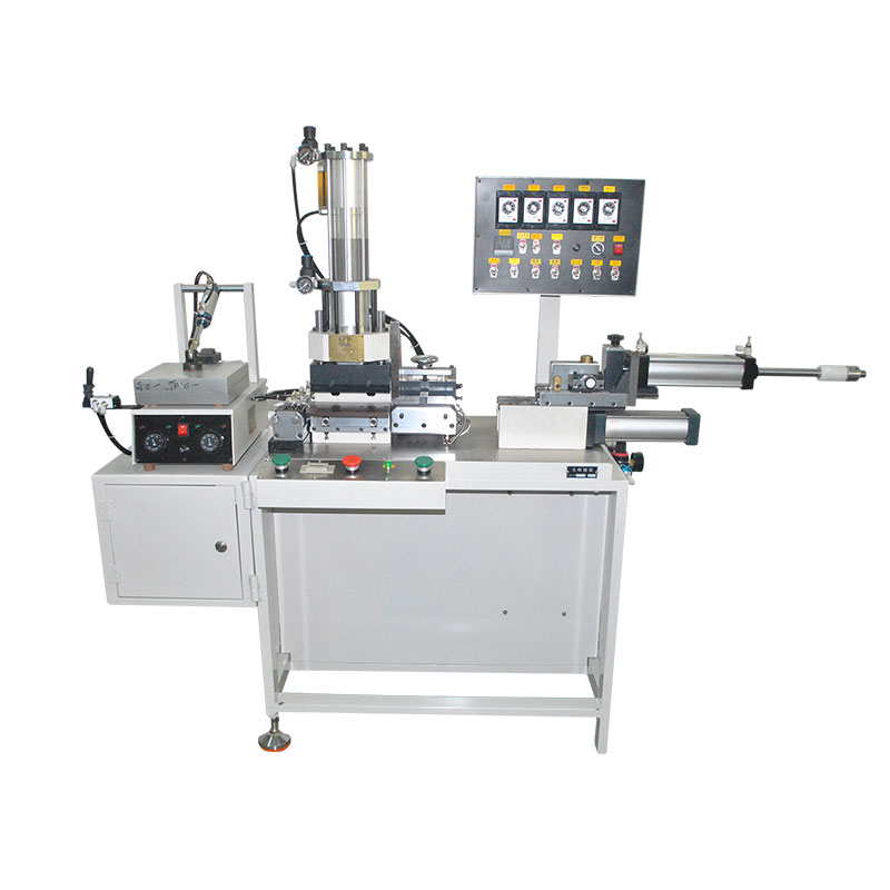
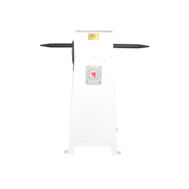
Manual Pile Cutting Machine II
Explosion-proof polishing machine for...
Environment-friendly double-head cutting...
Environment-friendly high-speed gong...
High-speed gong machine
Single axis copper core machine
New dual axis copper core machine
Nail glue machine
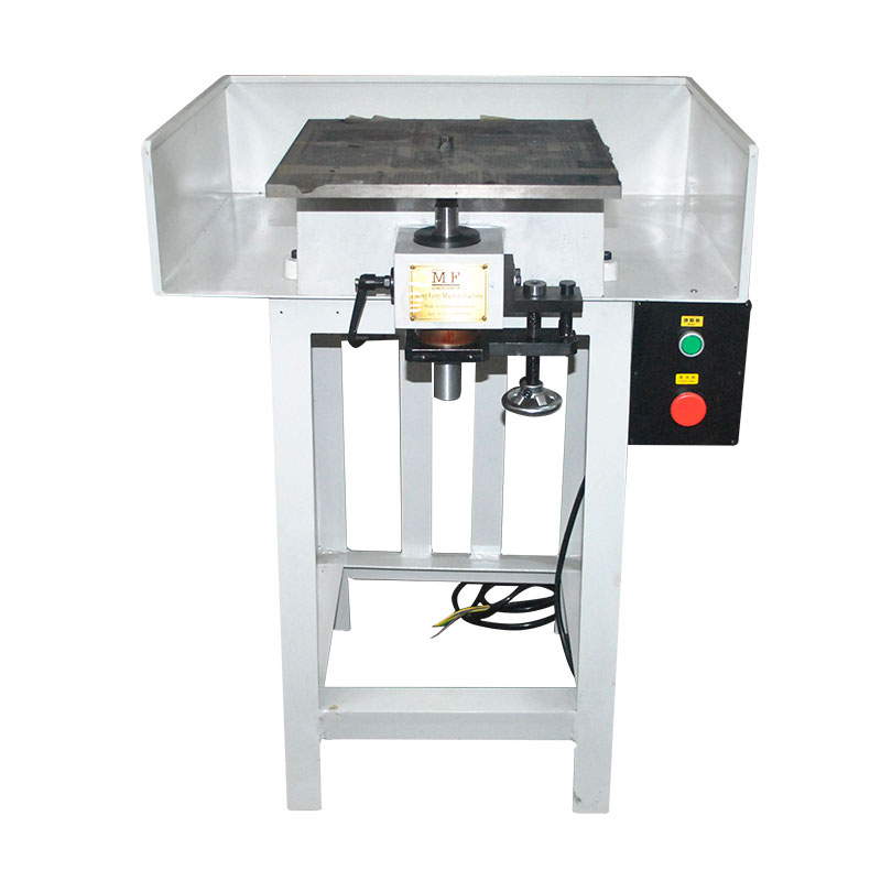
Planer
Hydraulic punching machine
Wind oil pressure planer
The new automatic three-sided planing...
Common problem HOME >> News >> Common problem
Background technique:
Glasses can be used to protect the eyes, such as radiation protection, anti-glare, etc., can also be used to correct vision problems such as nearsightedness, farsightedness, and astigmatism, and improve visual function. At the same time, the eyes can also be used as fashion items to decorate the face The outline, such as sunglasses, protects the eyes from the strong light under the strong sunlight, and also has a decorative effect. The structure of spectacles includes spectacle frames and spectacle lenses, and from a material point of view, frame glasses can be divided into sheet spectacle frames, titanium frames, metal alloy spectacle frames, and so on. The spectacle frame includes a spectacle frame and a temple, and the spectacle frame and the temple are usually connected by a hinge. However, in the existing hinge connection assembly process, it is generally completed by manual operation. In this processing method, the assembly speed is slow, error-prone, and the efficiency is low. It is difficult to ensure the assembly quality and affect the quality of the glasses.
Technical realization elements:
In order to overcome the deficiencies of the background technology, the utility model provides a glasses nail hinge machine, which mainly solves the problems of low assembly efficiency and poor effect in the existing glasses hinge assembly process. The structure of the glasses nail hinge machine is simple and reasonable. The automatic feeding method of the hinge parts improves the working efficiency of the hinge assembly. At the same time, the controller I and the controller II are used to control the whole machine, which improves the automation and assembly accuracy, ensures the quality of the glasses assembly, and greatly improves the glasses nails. The overall performance of the reaming machine is simple and practical, high efficiency, long service life, low cost and easy to promote.
The technical scheme adopted by the utility model is: a spectacle nail hinge machine, which includes a machine base, a clamping device, a working platform device and a vibrating plate. The machine base includes an integrated frame and a base, the frame The controller I and the controller II are arranged on the upper end of the frame, and a clamping device and a vibrating plate are arranged. The feeding cylinder and the feeding hose are arranged at the outlet of the vibrating plate, and the frame is also provided with the feeding cylinder. The air pump is equipped with a photoelectric counter on the feed cylinder, the feed hose is connected to the clamping device, and the working platform device is provided on the base. The working platform device includes a front and rear fixed seat fixedly connected to the base. Front and rear guide seats and front and rear electric cylinders, left and right guide seats are provided with left and right guide seats and left and right electric cylinders, left and right guide seats are provided with a bottom plate and an angle motor I, and a work platform and an angle motor II are provided on the bottom plate; the clamping The device includes a fixture fixing frame, a fixedly connected lifting electric cylinder is arranged in the middle of the fixture fixing frame, a speed regulating valve is arranged on the lifting electric cylinder, and the lifting activity of the lifting electric cylinder is An infrared sensor I is arranged on the rod, and the upper and lower ends of the lifting piston rod are respectively provided with an upper bracket and a lower bracket. At least two lifting rails which cooperate with the lifting electric cylinder are arranged between the upper bracket and the lower bracket. A sleeve fixedly connected with the fixture fixing frame is provided; the lower end of the lower bracket is provided with a fixture mounting plate, and a left fixture and a right fixture corresponding to each other are provided on the lower side of the fixture mounting plate, and the left fixture is fixed to the fixture mounting plate by screws Connection, a clamping head that cooperates with the working platform is provided between the left clamp and the right clamp; a clamp electric cylinder fixedly connected to the clamp mounting plate is provided on the right side of the clamp mounting plate. The right clamps are fixedly connected to each other, and an infrared sensor II is provided on the electric cylinder of the clamp; the vibration plate includes a storage bin and a chassis fixedly connected, a spiral track is provided in the storage bin, and an electromagnetic vibrator is provided in the chassis; The controller I and the clamping device are electrically connected to each other. The controller I includes a display screen I, a control circuit I and a button assembly I. The control circuit I The lifting electric cylinder and the clamp electric cylinder are electrically connected to each other; the controller II is electrically connected to the working platform device and the vibrating plate respectively. The controller II includes a display screen II, a control circuit II and a button assembly II, and a control circuit II They are electrically connected to the front and rear electric cylinders, left and right electric cylinders, angle motor I and angle motor II, respectively.
The beneficial effects of the utility model are: due to the adoption of the above technical solution, the structure of the eyeglass nail hinge machine is simple and reasonable, and the working efficiency of the hinge assembly is improved by the automatic feeding method of the hinge accessories, and the controller I and the controller II are used at the same time. Control the whole machine, improve the automation and assembly accuracy, ensure the assembly quality of the glasses, greatly improve the overall performance of the glasses nail hinge machine, simple and practical, high efficiency, long service life, low cost, easy to promote.
1. Frame; 2. Base; 3. Controller I; 4. Controller II; 5. Feed cylinder; 6. Feed hose; 7. Air pump; 8. Photoelectric counter; 9. Front and rear fixed seat; 10 1. Front and rear guide seat; 11. Front and rear electric cylinder; 12. Left and right guide seat; 13. Left and right electric cylinder; 14. Base plate; 15. Angle motor I; 16. Working platform; 17. Angle motor II; 18. Fixture fixing frame; 19. Lifting electric cylinder; 20, speed control valve; 21, lifting piston rod; 22, infrared sensor I; 23, upper bracket; 24, lower bracket; 25, lifting rail; 26, casing; 27, fixture mounting plate; 28. Left clamp; 29, right clamp; 30, clamping head; 31, clamp electric cylinder; 32, clamp piston rod; 33, infrared sensor II; 34, storage bin; 35, chassis.
detailed description
The following further describes the embodiment of the utility model with reference to the drawings:
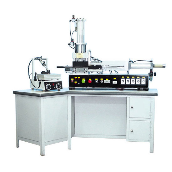
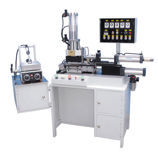
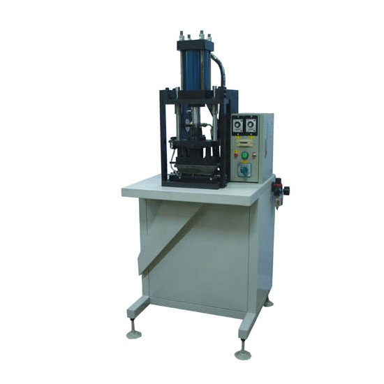
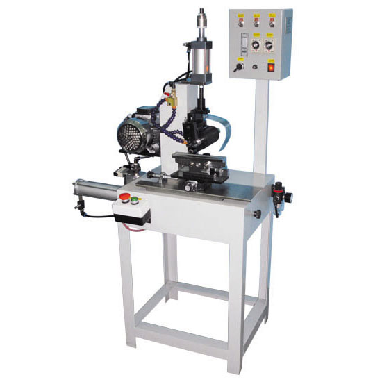
As shown in FIGS. 1 to 2, a spectacle nail hinge machine includes a machine base, a clamping device, a working platform device and a vibrating plate. The machine base includes an integrated frame 1 and a base 2, the machine The rack 1 is provided with a controller I 3 and a controller II 4, the upper end of the rack 1 is provided with a clamping device and a vibration plate, a hinge fitting is provided in the vibration plate, a feed cylinder 5 and a feed soft are provided at the exit of the vibration plate Pipe 6, the rack 1 is also provided with an air pump 7 matched with the feed cylinder 5, the feed cylinder 5 is provided with a photoelectric counter 8 for counting hinge accessories, the feed hose 6 and the clamping device are connected to each other, The base 2 is provided with a working platform device. The working platform device includes a front and rear fixed seat 9 fixedly connected to the base 2. The front and rear fixed seat 9 is provided with a front and rear guide seat 10 and a front and rear electric cylinder 11. The front and rear guide seat 10 passes through the front and rear electric cylinder 11 Adjust the front and rear positions. The front and rear guide seats 10 are provided with left and right guide seats 12 and left and right electric cylinders 13. The left and right guide seats 12 are adjusted by left and right electric cylinders 13 to adjust the left and right positions. There are settings on 14 Angle of the motor 16 as a platform and II 17, the angle and the motor angle of the motor I 15 16 II 16 adjusting the inclination of the work platform to keep it level.
The clamping device includes a fixture fixing frame 18, and a fixedly connected lifting electric cylinder 19 is provided in the middle of the fixing frame 18, a speed regulating valve 20 is provided on the lifting electric cylinder 19, and a lifting piston rod 21 of the lifting electric cylinder 19 is provided An infrared sensor I 22 is provided. The infrared sensor I 22 is used to detect whether the lifting piston rod 21 is lifted in place, and the upper and lower ends of the lifting piston rod 21 are provided with an upper bracket 23 and a lower bracket 24, respectively. There are at least two lifting rails 25 that cooperate with the lifting electric cylinder 19, and the lifting rail 25 is sleeved with a sleeve 26 fixedly connected to the fixture fixing frame 18, and the sleeve 26 facilitates the lifting rail 25 to move up and down.
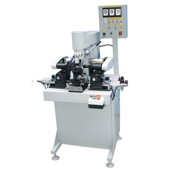
The lower end of the lower bracket 24 is provided with a clamp mounting plate 27, and the lower side of the clamp mounting plate 27 is provided with a left clamp 28 and a right clamp 29 corresponding to each other. The left clamp 28 is fixedly connected to the clamp mounting plate 27 by screws, and the left clamp 28 A clamping head 30 that cooperates with the working platform 16 is provided between the right clamp 29 and the right clamp 29.
The right side of the clamp mounting plate 27 is provided with a clamp electric cylinder 31 fixedly connected thereto. The clamp electric cylinder 31 is fixedly connected with the right clamp 29 by setting a clamp piston rod 32, and an infrared sensor II 33 is provided on the clamp electric cylinder 31 Infrared sensor II 33 is used to detect whether the movement position of the electric cylinder 31 of the clamp is in place.
The vibrating plate includes a storage bin 34 and a chassis 35 that are fixedly connected. A spiral track is provided in the storage bin 34, and an electromagnetic vibrator is provided in the chassis 35.
The controller I 3 and the clamping device are electrically connected to each other. The controller I 3 includes a display screen I, a control circuit I and a button assembly I. The control circuit I is electrically connected to the lifting electric cylinder 19 and the clamp electric cylinder 31 respectively Connected, the button assembly I includes a raising button and a lowering button of the lifting electric cylinder and a left-moving button and a right-moving button of the jig electric cylinder.
The controller II 4 is electrically connected to the working platform 16 device and the vibration plate respectively. The controller II 4 includes a display screen II, a control circuit II and a button assembly II. The control circuit II is connected to the front and rear electric cylinders 11, left and right respectively The electric cylinder 13, the angle motor I 15 and the angle motor II 17 are electrically connected to each other.
The structure of the glasses nail hinge machine is simple and reasonable. The automatic feeding method of the hinge accessories improves the working efficiency of the hinge assembly. At the same time, the controller I 3 and the controller II 4 are used to control the whole machine, which improves automation and assembly precision The degree guarantees the assembly quality of the glasses and greatly improves the overall performance of the glasses nail hinge machine. It is simple and practical, high in efficiency, long in service life, low in cost and easy to promote.
Note to technicians: Although this utility model has been described according to the above specific embodiments, the inventive idea of this utility model is not limited to this utility model. Any modification that uses this inventive idea will be included in the scope of protection of the patent rights of this patent Inside.
Previous:The origin and development of ...
Next page:Manufacturing method of high...
What is the manufacturing method of the automatic glasses foot bending machine?
2020-05-21
The formation of the eyewear industry
2020-05-21
The origin and development of glasses
2020-05-21
Making method of glasses nail hinge machine
2020-05-21
Manufacturing method of high-efficiency automatic numerical control glasses frame...
2020-05-21
Contact: Miss Shen
Mobile: +86-13509635423
TEL: +86-0755-28692123
FAX:+86-0755-28692277
E-mail:chinamf@mf789.com
Address: No. 35, Dayuan Street, Silian Community, Henggang Street, Longgang District, Shenzhen

WeChat scan code
SHenZHen Mingfeng Machinery Equipment Co. ,Ltd. Shenzhen Mingfeng machine equipment Co. Ltd.Copyright 2016-
Mingfeng Machine © Copyright
Technical Support:XINQI
 English
 简体中文
简体中文 HOT searches: